
Gravitational Physics and Lunar Structure
The second research goal fo the LUNAR team is to probe the interior structure of the Moon using accurate measurments of the Earth-Moon distance using small retro-reflectors placed on the lunar surface. Several reflectors are already sitting on the Moon, placed by Apollo astronauts and Soviet lunar landers. However, the technology is 40 years old, and significant scientific improvments can be made with newer, more accurate reflectors. Besides looking underneath the lunar crust, these reflectors can be used to test several astronomical theories.
Scientific Motivations
An enduring legacy of Apollo is the Lunar Laser Ranging (LLR) package, which is a series of lunar retro-reflectors scattered about the lunar nearside. These reflectors have been used to test alternate theories to General Relativity (GR) and to probe the nature of the lunar core. Current alternate theories for gravity, including those that explain dark matter and dark energy, predict deviations from GR at a level that is potentially within the grasp of the next generation of LLR.
Theoretical Tools
The LLR team of the LUNAR group has been addressing the design, fabrication and emplacement of the next generation of retroreflectors for the moon.
- These can improve the accuracy, and thus the science, by a factor of more than 100.
- Many different retroreflector designs have been developed and their performance in the lunar environment simulated in various computer programs. The best designs have been implemented in hardware and tested in thermal vacuum chambers to evaluate their performance in the harsh environment on the lunar surface.
- In addition, the method of deployment on the lunar surface is critical for maintaining the accuracy. Various methods of deployment have been devised and some of these have been tested in the laboratory and recently in NASA organized field tests in areas on earth that have been deemed similar to the lunar soil (Mauna Kea volcano in Hawaii).
- The ground station requirements are being explored by LLR from the LRO satellite.
- We are also investigating the accuracy of the software programs to the analysis of the data and are working to improve areas of weakness.
A total lunar eclipse on 2010 December 21 provided an opportunity to test ideas about the observed LLR signal deficit at full moon. In marginal observing conditions, the Apache Point Observatory Lunar Laser-ranging Operation (APOLLO) project was able to confirm that the removal of sunlight resulted in far better signal performance than has been previously seen by APOLLO at full moon. It also appears that the signal improves early in the eclipse, then gets worse, and briefly becomes strong again when the light returns. This matches expectations if solar absorption at the corner cube front surface establishes a thermal gradient that causes the signal degradation. When the sunlight is removed, the gradient temporarily disappears, then changes sign as the corner cube prism cools by radiating to space. When the light returns, the gradient swings through zero again as it re-establishes a warmer front surface. This new information will help constrain models of what causes the deficit, and will contribute to the nextgeneration reflector designs that seek to avoid a similar fate.
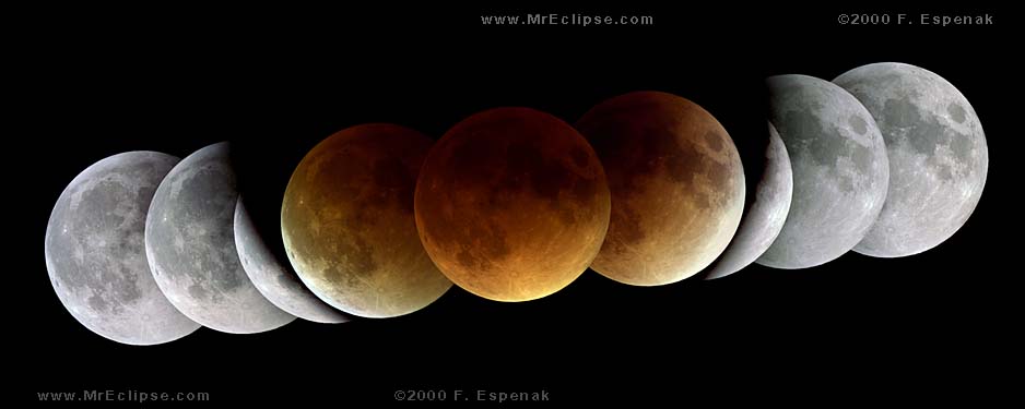
Figure 1: Image compiled by an ameteur astronomer of a total lunar eclipse. This one occured in 2003.
Much effort during the first year of LUNAR was spent refining the science case for new LLR capabilities. The possibility of testing modified General Relativity using LLR was explored. In conjunction with testing GR, the laser clean room at the 1.2m Telescope Tracking Facility at the Goddard Geophysical and Astronomical Observatory (GGAO) in Greenbelt Maryland was converted to support the capture and analysis of cube corner Far Field Diffraction Patterns (FFDP). This laboratory with remote access to the telescope Coude’ room originally housed high power short pulse lasers for Satellite Laser Ranging (SLR) operations.
The once lost Russian lunar rover Lunokhod 1 has been found thanks to the LROC camera on board the Lunar Reconnaissance Orbiter (LRO). This rover was installed with retro-reflectors different from those deployed by Apollo astronauts. Check out this paper on how the addition of another lunar laser reflector helps constrain our theories about the structure of the lunar interior. After its discovery in March of 2010, it was subsequently ranged by Murphy and colleagues the following month. The coordinates---previously unknown at the 5 km level---are now pinned down to within a few cm.
Surprisingly, the Lunokhod 1 reflector performs about four times more strongly than its twin on Lunokhod 2. This provides an interesting wrinkle in the story of degradation of the reflectors, as reported in the first annual report for LUNAR. Lunokhod 2 was once comparable in strength to Apollo 15, but is now ten times weaker than Apollo 15. Lunokhod 1, by contrast, is only a factor of two weaker than Apollo 15. Since the two Lunokhod reflectors share the same design, we are faced with the mystery of why Lunokhod 2 has degraded much faster than has Lunokhod 1 (meanwhile, the Apollo 15 array has degraded significantly as well). The location of Lunokhod 1 on the moon---the closest reflector to the apparent limb---makes it the most sensitive probe of lunar orientation. Having five available reflectors on the moon bolsters our ability to map tidal distortions of the lunar figure. Finding Lunokhod 1 is also a useful trial case of "installing" a new reflector on the moon, and adapting analysis efforts to utilize the new data.
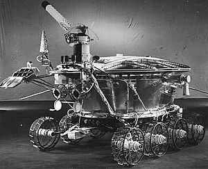
Figure 2: A image released by the Soviet Union of the Lunakhod 1 rover before deployment in 1970. Lunakhod means 'Moon-walker' in Russian.
Technology Development
From previous testing of commercial hollow corner cubes, it was concluded that the currently available cubes are unlikely to perform well when scaled up to the size required for new lunar retroreflectors. Therefore, efforts were focused on developing in-house capabilities for assembling hollow cubes using a technique known as hydroxide-catalysis bonding. This technique uses a small amount of sodium silicate solution to produce a thin bond between glass materials while providing significant strength over a large temperature range. A considerable amount of work was done to determine how the bond will change the positions of the facet flats as the bond sets, characterizing the bonding technique to determine the amount of solution to be used, how to administer the solution, and establishing the alignment procedure using hydroxide bonding.
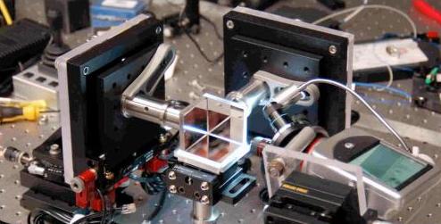
Figure 4: This is one of our next generations of Corner Cube Reflectors CCR to help constrain our distance measurements from the Earth to the Moon. This particular CCR design is looking into the adhesives used to bond the mirrors precisely.
In order to simulate the overall performance of the LLRRA-21, the thermal properties of the lunar regolith, the housing of the CCR and the CCR have been modeled. This has been done using data on the regolith from the Apollo missions and the properties of the elements of the housing and the fused silica of the CCR. Several housing types have been modeled. The best selection is shown in Figure 5. This model must be compatible with the drilling system used to deployment, discussed below.
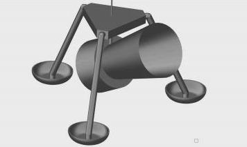
Figure 5: A corner cube reflector sitting inside its starshade. The tripod design has since been abandoned in favor of drilling into the regolith for thermal control.
Another component of the next generation corner cube reflector (CCR) has been design and testing of a pneumatic drilling system to help thermally isolate the CCR’s on the lunar surface. Drilling the CCR into the regolith keeps the temperature of the reflector steady to within s tiny fraction of a degree. This will allow far greater accuracy in the measurement of its location, since the thermal expansion and contraction of the Apollo era reflectors causes a large uncertainty in the measurements. The drill does not screw into the regolith, which cost the Apollo astronauts several hours to accomplish. Instead, a gas cartridge is placed on top of a hollow spear. The gas coming out of the tip blows the dust out of the way, and the weight of the drill causes it to sink further into the surface.
A successful field test of the pneumatic drill was performed at the CSA/NASA/DRL test site at Mauna Kea, Hawaii, Hawaii in January 2011. The pneumatic drill, weighted only by the CCR and the CCR housing, penetrated to about one meter when the compressed air was injected in the tip of the drill bit.Modifications to the drill are already being designed for use on a rover. A preliminary design, based on another similar concept has been completed and indicates that the procedure for the LLR retroreflector array should be feasible.
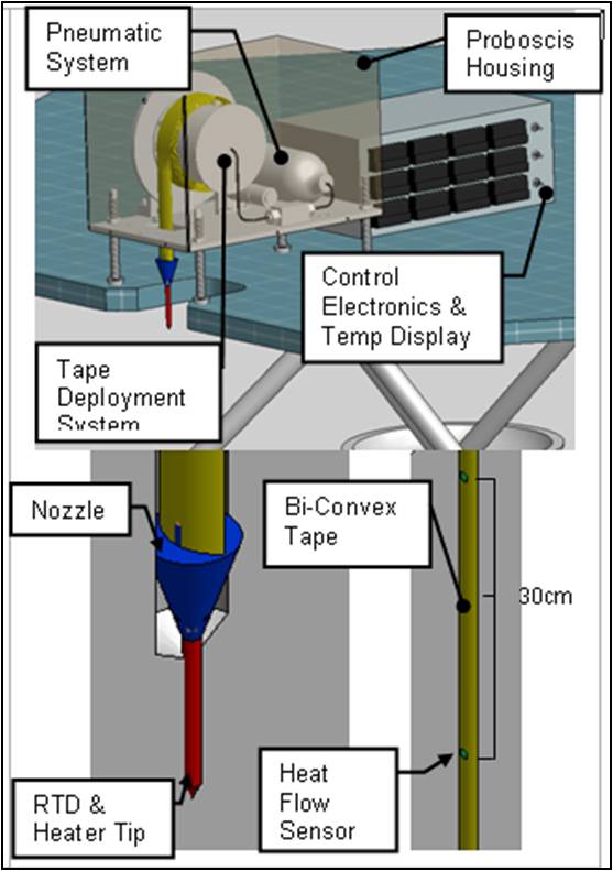
Figure 6: A schematic of the Pneumatic gas drill being developed and tested for use with the next generation of Lunar Laser Reflectors. This drill is a necessary part of anchoring the reflectors to solid rocks beneath the regolith on the surface of the Moon.


